After 3M Exited PFAS: Selection Logic and Verification Checklist for Domestic Replacement of Electronic Fluorinated Fluids
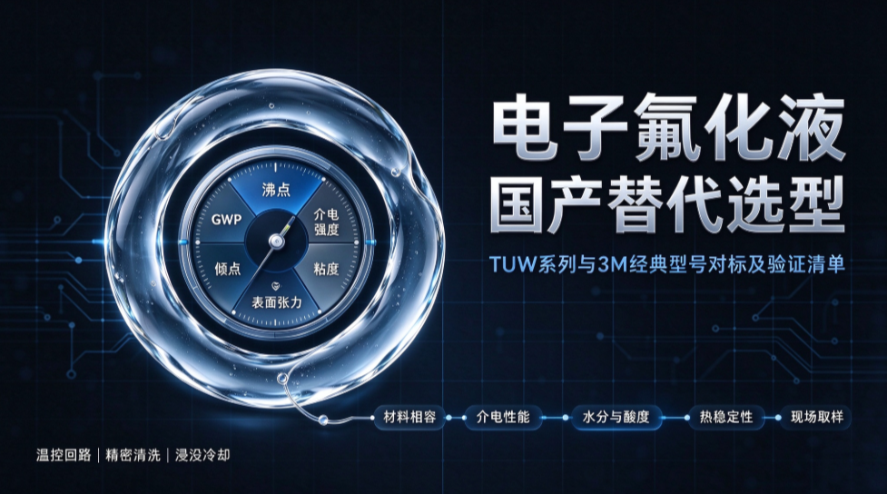
After 3M announced its exit from the PFAS business, many engineers working on temperature control and cleaning for electronic equipment immediately looked for a comparison table: Novec 7200 versus TUW-7200, FC-3283 versus TUW-3283 — match the model number and the swap is done. In practice they discover that matching the model number is only the entry ticket. What really decides whether a swap is possible is whether boiling point, dielectric strength, viscosity and material compatibility all fall inside the operating window at the same time.
This article breaks domestic replacement into four questions: where to start, what level the fluid's physical properties reach, how the equipment operating conditions map after the change, and what to confirm before going on line.
I. After 3M's Exit, Where Should Domestic Replacement Start?
(A) What Exactly Is Being Replaced
3M's electronic fluorinated fluids fall roughly into two families. One is hydrofluoroethers (HFE), with low boiling points, low viscosity and relatively manageable GWP, mainly used in precision cleaning, leak testing and low-temperature constant-temperature baths. The other is perfluorinated compounds, including perfluorinated amines and perfluorocarbon liquids, with high boiling points, good insulation and strong chemical inertness, mainly used in semiconductor temperature-control loops and in cooling for etchers and ion implanters.
The replacement logic is not the same for the two families. For HFE, what matters is whether the solvency and drying speed match the contaminants; for perfluorinated compounds, what matters is dielectric strength, volume resistivity and long-term thermal stability, because these fluids often contact live parts directly or sit in high-temperature loops. Determine first which line you are replacing, and only then does selection become meaningful.
(B) Why Matching a Model Number Does Not Mean a Drop-In Swap
A boiling point difference of a dozen degrees sounds small, but it changes the evaporation rate, the make-up frequency and the drying rhythm of the whole loop. A slightly higher viscosity means the pump head and flow have to be recalculated, and the heat exchanger's heat transfer coefficient changes with it. A different surface tension changes how the fluid penetrates microchannels and multilayer structures, so cleaning dead corners and drain-down times for immersion both shift.
One more item is often overlooked: material compatibility. Whether seals, gaskets, pump diaphragms and plastic parts swell, harden or leach after prolonged contact can only be confirmed by immersion tests, not inferred from a data sheet.
II. What Level Do the Physical Properties of the TUW Series Reach?
(A) Six Key Properties Are Enough
The first is boiling point or boiling range: it determines the temperature range in which the fluid can work, how fast it evaporates and whether reflux condensation is needed. The second is dielectric strength and volume resistivity: these determine whether the fluid can contact live parts directly. The third is viscosity: it determines pump selection and heat transfer efficiency.
The other three are surface tension, pour point and GWP. Low surface tension means better wetting and penetration of microstructures; the pour point decides whether the fluid freezes in low-temperature environments; GWP is the item that comes up in compliance and customer audits. The TUW series covers the common operating windows on these items; the differences between individual models are shown in the table below.
(B) Order-of-Magnitude Comparison Between TUW and Classic 3M Models
The table below sets the TUW series alongside classic 3M models. The point is not digit-by-digit comparison but whether the key items fall within the same order of magnitude. As long as boiling point, dielectric strength, viscosity and density line up, the remaining differences can usually be absorbed by fine-tuning process parameters.
It should be noted that for models not listed here (such as TUW-449) that are not on the official website, selection must be based on the actual TDS, not extrapolated from the pattern of the series.
Table 1 Mapping of the TUW series against classic 3M models and key parameters
|
TUW model
|
3M counterpart
|
Chemistry
|
Boiling point (°C)
|
Density (g/mL, 25 °C)
|
Dielectric strength
|
GWP
|
Main applications
|
|
TUW-7500
|
Novec 7500
|
HFE
|
134
|
1.626
|
—
|
1
|
Immersion cooling, semiconductor temperature control
|
|
TUW-7200
|
Novec 7200
|
HFE
|
76
|
1.42
|
40 kV
|
55
|
Precision cleaning, leak testing, constant-temperature bath
|
|
TUW-7300
|
Novec 7300
|
HFE
|
98
|
1.6
|
>25 kV
|
297
|
Equipment temperature control, precision cleaning
|
|
TUW-7100
|
Novec 7100
|
HFE
|
61
|
1.52
|
—
|
320
|
Precision cleaning, cooling, solvent
|
|
TUW-3283
|
FC-3283
|
PFC
|
128
|
1.83
|
44 kV
|
118
|
Temperature control for etching and ion implantation equipment
|
|
TUW-40
|
FC-40
|
PFC
|
155-160
|
1.82
|
40 kV
|
175
|
High-temperature control, leak testing, insulation testing
|
|
TUW-770
|
FC-770
|
PFC
|
95
|
1.793
|
>40 kV
|
—
|
Direct cooling for supercomputing and military electronics
|
|
TUW-347
|
HFE-347
|
HFE
|
56.2
|
1.487
|
approx. 30 kV
|
—
|
Precision cleaning, drying, dust removal
|
|
TUW-458
|
HFE-458
|
HFE
|
93.2
|
1.533
|
40 kV/mm
|
—
|
High-purity cleaning, electrolyte co-solvent
|
|
TUW-71DA
|
Novec 71DA
|
HFE azeotrope
|
40
|
1.33
|
—
|
157
|
Degreasing, flux cleaning
|
Note: the values above are typical; refer to the corresponding product TDS and the batch COA. GWP is stated on a 100-year time horizon.
III. After Switching Fluids, How Do the Equipment Conditions Map?
(A) Temperature Control, Immersion and Cleaning Are Three Different Lines
A temperature-control loop cares about heat transfer capability, dielectric strength and long-term thermal stability; the fluid usually circulates in a closed loop, where moisture and particles are the main enemies. Immersion cooling cares about volumetric flow, dielectric performance and material compatibility, because the fluid has to sit around servers and power modules for long periods. Precision cleaning cares about solvency, boiling point and drying speed, and how the step dovetails with downstream processes.
Mix the three lines together and the most likely outcomes are using a cleaning fluid to soak live parts, or using a high-boiling-point fluid for fast-paced drying. Neither works well.
(B) How Scenarios Map to Models
The table below gives recommended model ranges for typical scenarios. It is a starting table, not a final selection table: the final choice still has to be confirmed against equipment materials, loop structure and the customer's acceptance criteria.
If the same equipment needs both temperature control and cleaning, select for the more demanding end and compensate on the other through process adjustments. Do not choose a model that is merely "about right" for both and excels at neither.
Table 2 Typical application scenarios and recommended models
|
Application scenario
|
Recommended model
|
Reason for selection
|
|
Immersion cooling for AI servers and energy-storage PACKs
|
TUW-7500, TUW-7100
|
Balanced boiling point and viscosity, good insulation, low GWP
|
|
Temperature control for semiconductor etchers and ion implanters
|
TUW-3283, TUW-40
|
Single-phase heat transfer, no component fractionation, covers -50 to 160 °C
|
|
Direct-contact cooling for supercomputing and military electronics
|
TUW-770
|
Pour point as low as -127 °C, dielectric strength >40 kV
|
|
Precision cleaning of PCBA, optical and medical parts
|
TUW-7100, TUW-347, TUW-458
|
Low surface tension, fast drying without residue
|
|
Leak-testing and constant-temperature bath media
|
TUW-7200, TUW-40
|
High density and low surface tension, no corrosion of the tested part
|
|
Carrier solvent for coatings
|
Used with TUW-2704 and TUW-1700
|
HFE carrier, forms a uniform film after evaporation
|
Note: actual selection must be confirmed together with equipment materials, seal grades, process temperature and cleanliness requirements.
IV. What Needs to Be Confirmed Before Going On Line?
(A) Four Laboratory Tests
Once these four are done, the situation where the parameters look right but the machine misbehaves is largely ruled out. The sample volume does not need to be large, but the conditions should be close to the real operating temperature and duration.
Material compatibility: immerse seals, gaskets, pump diaphragms and plastic parts, then measure changes in mass, volume and hardness.
Dielectric performance: measure dielectric strength and volume resistivity at the operating temperature, not only the room-temperature value.
Moisture and acidity: measure the initial water content and confirm that packaging and transport did not introduce moisture.
Thermal stability: after prolonged high-temperature storage, check appearance, color and drift in key properties.
(B) Three On-Site Verification Steps
Step one, no-load circulation: check whether the pump, flow and pressure are stable, and whether the return line carries bubbles. Step two, loaded operation: observe whether the temperature-rise curve and the temperature difference at the heat-exchange end fall within design values. Step three, continuous operation with fluid sampling: measure moisture, particles and appearance.
Only after all three pass should a full re-test be run for each batch, bringing the supplier's batch-to-batch consistency into the acceptance criteria. Replacement is not a one-off fluid change; it is the beginning of a long-term supply relationship.
Shenzhen Huayi Xiongdi focuses on the supply of electronic fluorinated fluids and fluorine-containing functional liquids. For sample testing or selection advice for a specific process, please use the consultation link on the right.
Introduction to Perfluoropolyether (PFPE)