TUW-3283 Electrolytic Fluorinated Carbon Liquid: From Process Principles to Semiconductor Equipment Temperature Control Applications

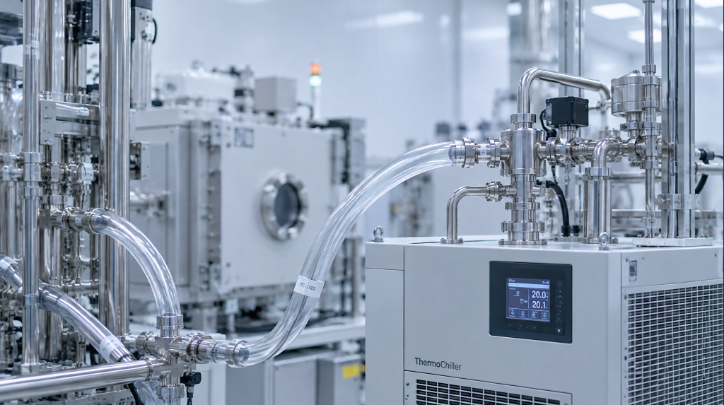
In the equipment bays of a semiconductor fab, etchers, ion implanters, and CVD tools run continuously, and the temperature inside the chambers must be controlled within a few tenths of a degree. Supporting this precision are closed-loop temperature control circuits — and the fluorinated carbon liquid flowing through them is often the "silent hero" that determines temperature control stability.
As international fluorinated-liquid manufacturers gradually adjust their PFAS product lines, the supply uncertainty of classic models such as FC-3283 is increasing, making domestic substitution an urgent need. However, the quality of products marketed as "benchmarked against FC-3283" varies widely, and the most critical differentiator is whether the production process is electrolytic (ECF). This article systematically reviews TUW-3283 from four dimensions: process principles, physical property parameters, semiconductor applications, and selection practices.
I. Why Semiconductor Equipment Depends on Fluorinated Carbon Temperature Control Liquids
Let's first understand a basic question: Why can't semiconductor equipment use water or ordinary oil for temperature control?
Take plasma etching as an example. Process gases are ionized into plasma by RF electric fields and bombard the wafer surface to etch it. During this process, the chamber walls, electrostatic chuck (ESC), and electrodes all generate substantial heat. If the temperature drifts by 1–2 degrees, the etch rate and uniformity will deviate noticeably from target values, directly affecting yield.
The requirements for the temperature control medium are therefore very demanding:
- Chemical inertness: It must not corrode or swell metal chambers, seals, and O-rings over long-term contact.
- Electrical insulation: The temperature control circuit is adjacent to high-voltage RF electrodes and beamline components; the medium must be highly insulating.
- Non-flammability: Fabs have extremely high fire-safety requirements; the medium must not become a fire hazard.
- Wide temperature range: From the cold return from the chiller to the hot output from the process chamber, the medium must remain liquid throughout.
- Low viscosity: Pump head is limited; high viscosity slows loop response and increases energy consumption.
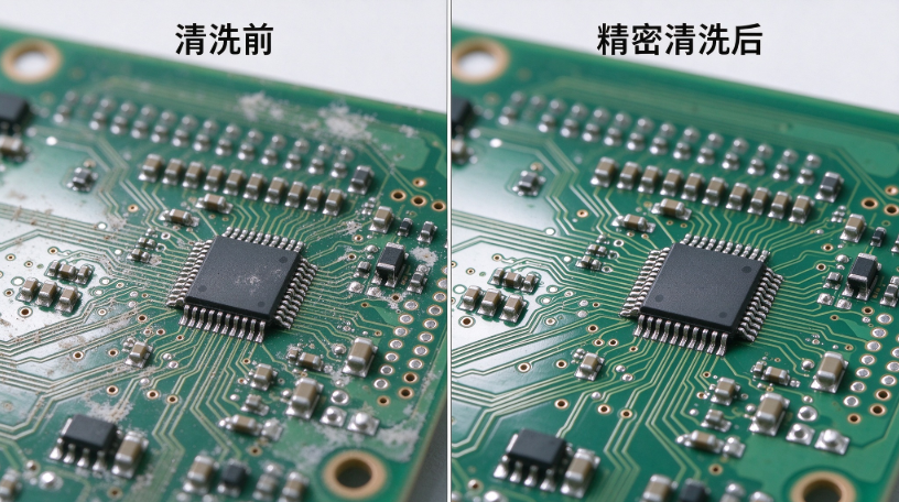
- Low evaporation residue: Semiconductor cleanliness requirements are high; the medium must not leave residue after evaporation.
Water has insufficient dielectric strength and a boiling point that is too low; ordinary oil is flammable and has poor insulation; alcohols corrode seals. Fluorinated carbon liquids are almost the only class of media that can simultaneously satisfy all of the above requirements.
II. What Is TUW-3283: An Electrolytic Fluorinated Carbon Liquid
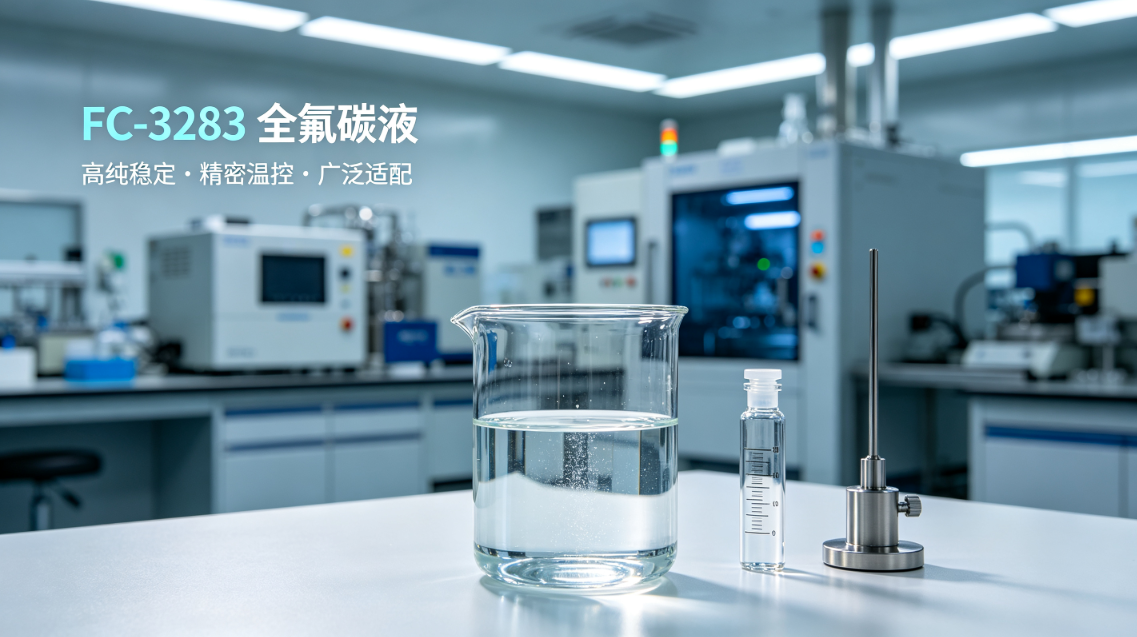
TUW-3283 is chemically a perfluorinated compound. Basic information is as follows:
| Parameter | Value |
|---|---|
| Product model | TUW-3283 |
| CAS No. | 86508-42-1 |
| Production process | Simons electrochemical fluorination (ECF) |
| Appearance | Colorless transparent liquid |
| Molecular weight | 500 |
| Chemical class | Fluorinated carbon liquid (PFC) |
The word "electrolytic" needs special explanation here. It refers to the Simons electrochemical fluorination process: the organic feedstock is dissolved in anhydrous hydrogen fluoride, with nickel as the anode and a steel tank as the cathode, and direct current is applied. Under the electric field, hydrogen atoms on the organic molecules are replaced one by one by fluorine atoms, ultimately producing perfluorinated compounds. The 3M original FC-3283 uses this same process.
It should be clarified that electrolysis is the production process, not the product's use. TUW-3283 is ultimately an insulating liquid with a dielectric strength of 44 kV; it does not conduct electricity.
III. Electrolytic Method vs. Chemical Synthesis Method: Why This Matters
Among domestic products currently marketed as benchmarked against FC-3283, there are two main process routes. Understanding their difference is the first step in selection.
Simons Electrolytic Fluorination (ECF) Fluorination is carried out by electrolysis in an anhydrous HF system, in a closed electrolytic cell. Its characteristics: high perfluorination conversion rate, few residual partially-fluorinated intermediates in the molecule; controllable reaction conditions, good batch-to-batch consistency; high thermal stability of the product, not easily decomposed during long-term high-temperature operation. The 3M FC-3283 original follows this route.
Chemical Synthesis Method Perfluorinated compounds are synthesized via fluorine gas addition or multi-step chemical reactions. This route has lower feedstock costs, but the product may retain incompletely fluorinated intermediates, isomers, and byproducts. In nominal parameters such as boiling point and density, chemical synthesis products may approach electrolytic products, but gaps exist in long-term high-temperature stability, batch consistency, and electrical insulation retention.
| Comparison dimension | Electrolytic method (TUW-3283) | Chemical synthesis method |
|---|---|---|
| Perfluorination rate | High, complete molecular structure | May contain partial fluorination impurities |
| Batch consistency | Electrolytic process controllable, low fluctuation | More affected by reaction conditions |
| Long-term thermal stability | Stable under high-temperature cycling, no decomposition | Impurity sites may decompose first |
| Volume resistivity retention | Stable at 10^14 order long-term | May gradually decline due to impurities |
| Evaporation residue | ≤ 100 ppm | May be higher |
| Applicable scenarios | Semiconductor temperature control, high-reliability testing | Ordinary cooling, purity-insensitive |
Objectively speaking, chemical synthesis products may be entirely adequate in ordinary industrial cooling scenarios and have a cost advantage. But in equipment such as semiconductor etchers and ion implanters, where medium cleanliness and long-term stability are extremely demanding, using the wrong process route can cost an entire batch of wafers.
IV. TUW-3283 Core Physical Property Parameters in Detail
The following parameters directly affect the design and operation of semiconductor temperature control circuits:
| Parameter | Value | Engineering significance |
|---|---|---|
| Boiling point | 128 °C | Determines the upper limit of the hot tank; chiller outlet temperature is usually set 20–30 °C below this |
| Pour point | −65 °C | Determines the lower limit of the cold tank; prevents freezing after shutdown in winter |
| Density | 1.83 g/cm³ | High density means strong heat storage per unit volume; heat exchangers can be more compact |
| Kinematic viscosity | 1.32 cSt | Low viscosity means low pump resistance, fast loop response, good temperature uniformity |
| Surface tension | 12.7 dyn/cm | Low surface tension aids penetration of microchannels and leak detection |
| Specific heat capacity | 1.431 J/g·°C | Determines how much heat can be removed per unit volume |
| Thermal conductivity | 0.0834 W/m·K | Affects heat transfer efficiency between the heat exchanger wall and the fluid |
| Dielectric constant | 1.96 | Low dielectric constant means less signal interference to high-frequency circuits |
| Volume resistivity | 1.36×10¹⁴ Ω·cm | Highly insulating; safe to contact live components |
| Dielectric strength | 44 kV | High breakdown voltage, low short-circuit risk |
| Flash point | None | Non-flammable; lowers the fab fire-safety classification requirement |
V. Specific Applications in Etchers
In plasma etching, two locations require precise temperature control:
The first is the electrostatic chuck (ESC). The wafer backside is electrostatically held on the ESC for etching, and the ESC temperature directly affects photoresist curing behavior and etch selectivity. If the ESC temperature is unstable, the etch rate across different areas of the wafer surface becomes non-uniform, manifesting as across-wafer CD (critical dimension) deviation.
TUW-3283 is pumped by an external chiller into the microchannels inside the ESC, carrying away the heat that the RF plasma deposits on the wafer. The specific heat capacity of 1.431 J/g·°C and thermal conductivity of 0.0834 W/m·K ensure efficient heat exchange, while the low viscosity of 1.32 cSt keeps flow resistance in the microchannels controllable.
The second is the chamber sidewall. During etching, polymer byproducts deposit on the chamber walls. If the wall temperature is too high or too low, deposit morphology becomes abnormal, leading to particulate contamination. TUW-3283 circulates in the chamber cooling jacket to maintain wall temperature within the set range.
Here the importance of electrolytic purity is again evident: the medium runs near high temperature and vacuum for extended periods. If it contains easily decomposed impurities, volatile acids or conductive residue may be produced, contaminating the chamber or forming an insulating layer on the ESC surface, affecting chucking performance.
VI. Applications in Ion Implanters
An ion implanter bombards the wafer surface with an accelerated ion beam to alter doping characteristics. Components along the beam path — including the target disk, beam deflection magnet, and wafer cooling disk — generate substantial heat under high-energy particle bombardment. Temperature drift causes non-uniform dose and junction depth deviation.
TUW-3283 circulates in the cooling circuits of these components to maintain precise temperature. Its volume resistivity of 1.36×10¹⁴ Ω·cm is especially critical — ion implanter beamline components carry high voltage, and the cooling circuit is adjacent to live structures. If the medium's insulation performance degrades, it can cause beam instability or even equipment failure.
VII. Quality Indicators and Batch Control
Semiconductor-grade applications impose strict quality control requirements on the medium itself:
| Indicator | Value | Why it matters |
|---|---|---|
| Purity (GC) | ≥ 99% | Impurities may decompose under high temperature to produce acid |
| Moisture | ≤ 50 ppm | Moisture may freeze and block microchannels at low temperature |
| Acid value | ≤ 10 ppm | Acid corrodes stainless steel tubing and seals |
| Evaporation residue | ≤ 100 ppm | Volatile residue contaminates the process chamber |
It is recommended to request a COA (Certificate of Analysis) for each batch when purchasing, and verify the four indicators above. If a supplier can only provide nominal TDS but no batch COA, exercise caution.
VIII. Environmental and Supply Considerations
| Indicator | Value |
|---|---|
| ODP | 0 |
| GWP (100-year) | 118 |
TUW-3283 has an ODP of zero and does not deplete the ozone layer. Its GWP of 118 is relatively low compared to some traditional PFCs, but still higher than hydrofluoroether (HFE) products. Customers exporting to Europe should monitor local PFAS regulatory developments.
On the supply side, overseas original manufacturers such as 3M have announced adjustments to their PFAS product lines, and FC-3283 faces long-term supply uncertainty. As a domestic electrolytic product, TUW-3283 offers more assured lead times and supply chain security.
IX. Practical Switchover Recommendations
Switching from FC-3283 to TUW-3283 is recommended in four steps:
Step 1 — Physical property comparison. Confirm that key parameters such as boiling point, density, viscosity, and specific heat are compatible with the existing circuit. TUW-3283 has a boiling point of 128 °C, matching FC-3283, and a density of 1.83 g/cm³, which is close.
Step 2 — Material compatibility. Immerse O-rings, sealants, and tubing from the circuit in TUW-3283 for 72 hours and observe swelling and corrosion. Electrolytic products are highly pure, so compatibility is typically consistent with the original.
Step 3 — Spare-machine trial. First run a complete production cycle on a non-critical tool, monitoring temperature control accuracy, pump pressure changes, and the medium's color and odor.
Step 4 — Batch switchover. After the trial runs without issues, roll out gradually, keeping a 1–2 month parallel period.
X. Product Positioning Summary
Based on the above analysis, TUW-3283 is suited to be positioned as:
An electrolytic high-purity fluorinated carbon liquid for temperature control of semiconductor etchers, ion implanters, and CVD equipment, as well as thermal shock testing and package leak testing.
Its core competitive strengths lie in: the Simons electrolytic production process benchmarked against the original manufacturer, a boiling point of 128 °C covering the mainstream semiconductor temperature control range, dielectric strength of 44 kV and volume resistivity of 10¹⁴ Ω·cm providing high-insulation assurance, and controlled quality indicators such as purity and moisture.
Shenzhen Huayi Brothers specializes in the supply of electronic fluorinated liquids and fluorine-containing functional liquids, providing customers with product documentation, sample testing, and application solution exchange. For sample testing, please contact: 15014124590 / 18870870567.
Related Article